A technical deep-dive for DIY enthusiasts
Introduction
Before we get into the details, let’s get one thing straight: if you just want a quick and easy solution, you’ll almost certainly be better off buying a pre-made brake kit. It’ll save you money, time, and frustration.
If you are just here for the drawings and 3D model – just skip to the bottom!
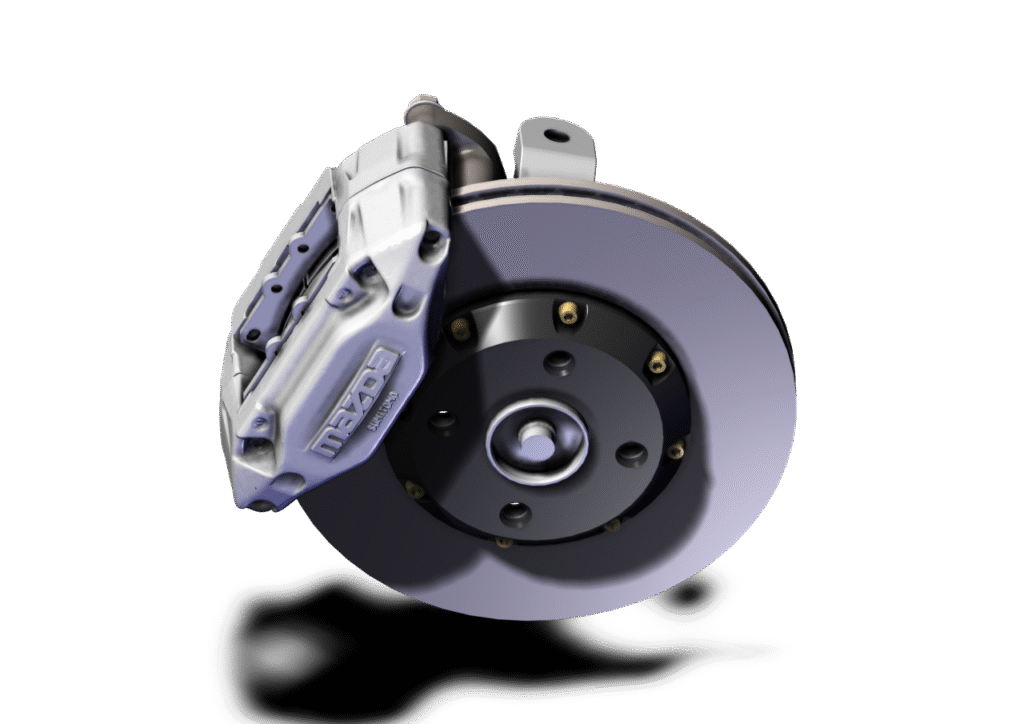
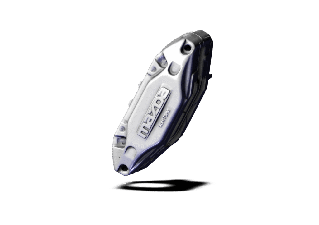
So why go down the custom path? For me, it wasn’t about performance — it was about curiosity, learning, and chasing a very particular look. I wanted FD3S RX-7 front callipers (which are nearly identical to the FC3S units) on my 2002 MX-5 SP.
For context: the RX-7 callipers are popular largely because of aesthetics. Having “MAZDA” visible through a set of open-spoke wheels is a cool look. In terms of performance, though, they aren’t a meaningful upgrade over the factory NB callipers when paired with good pads. If you’re chasing pure track performance, there are better callipers out there.
But the RX-7 callipers make an interesting case study, because although people have been doing this swap for years, it’s rarely been done well — or safely.
Why This Article Exists
What motivated me to write this wasn’t just the process of fitting callipers — it was the question of material choice for the brackets (often called “dog bones”).
If you look at almost every off-the-shelf kit, you’ll see “aerospace grade aluminium” advertised (they usually mean 6061-T6). Sounds impressive, right? Unfortunately, when you dig deeper, it can be incredibly dangerous depending on how the assembly works.
I ended up using 4340QT steel, even though it was more expensive and required a much larger stock piece. The decision wasn’t about strength alone — it was about reliability. And the difference in philosophy between “making parts” and “engineering solutions” is something worth unpacking.
Background
I first spotted an NA MX-5 online with RX-7 callipers years ago. It looked brilliant, and I knew I’d eventually try it. But when I dug into forum posts, I kept finding the same thing: people running into serious fitment and safety issues. So I shelved the idea. You can find a forum post here discussing some of the issues this user found with the conversion.
Fast forward a few years, I saw companies advertising “kits” for the conversion. I asked two suppliers how they solved the well-known interference issues. One flatly denied they existed, the other dodged the question.
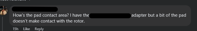
This is a recurring theme with aftermarket car parts. With modern access to CAD, 3D printers, and scanners, it’s easier than ever to make a product. But “making” something isn’t the same as engineering it. Engineering means considering safety, fatigue, tolerances, and usability — things many parts skip. The comment below was made when I was sharing some details about my attempt at this conversion. Even something as simple as getting the pads to contact the rotor is skipped by companies that sell a “product”.
Solution 1 – The Typical Bracket
This is the solution you’ll see online or in off-the-shelf kits – such as the one in the comment above.
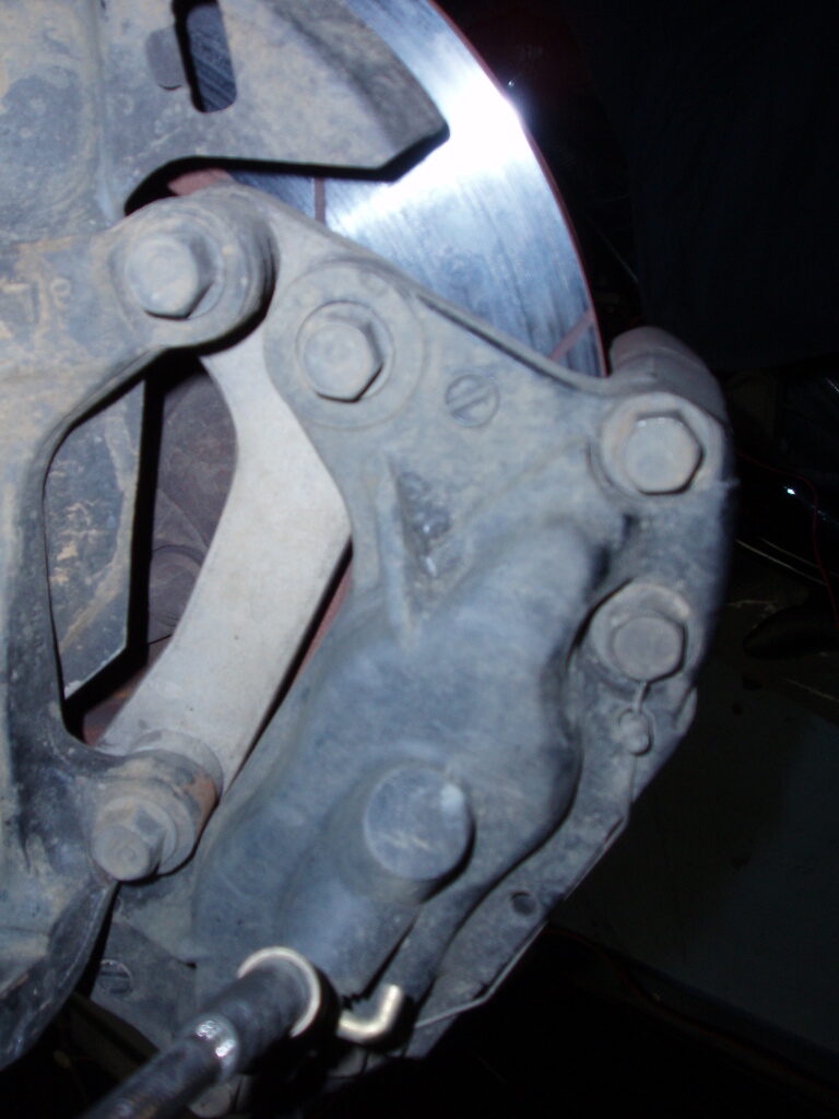
It involves a simple dog bone bracket that bolts the RX-7 calliper to the MX-5 hub. Straightforward in theory, but in practice:
- Requires a non-standard rotor size (minimum ~290mm).
- Creates interference between calliper lugs and hub mounts.
- Reduces steering angle significantly.
- Often requires a wheel spacer.
- Does not clear 15” rims (a dealbreaker for many MX-5 owners).
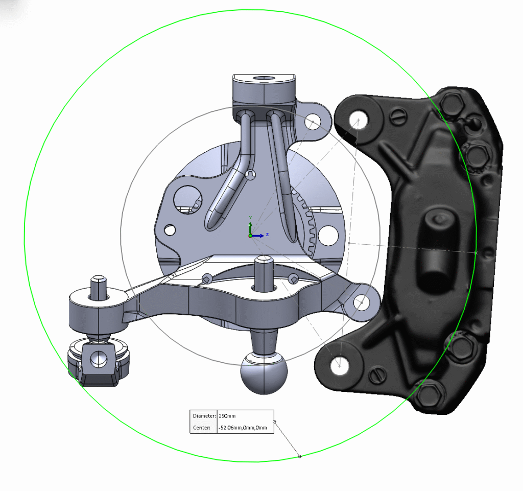
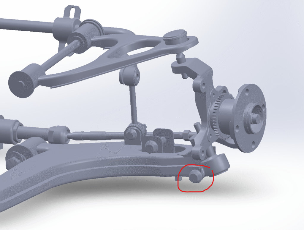
In my own CAD modelling, I quickly discovered the same issues. Most critically, the lower calliper bolt collides with the lower control arm bolt. No amount of tweaking solves it.
If you’re building a dedicated track car, maybe that loss of steering angle isn’t a big deal. But then again, for a dedicated track car, you wouldn’t be choosing RX-7 callipers in the first place.
Bottom line: Every bracket of this type on the market has these flaws.
Solution 2 – Lightly Modified Calliper
Some people try shaving a little material from the calliper lugs or knuckle to make things clear. This can allow fitment with certain rims, but it doesn’t solve the big issues:
- You still need a large rotor (~305mm minimum).
- 15” rims are still a no-go.
- Interference is reduced but not eliminated.
It’s a compromise on top of a compromise.
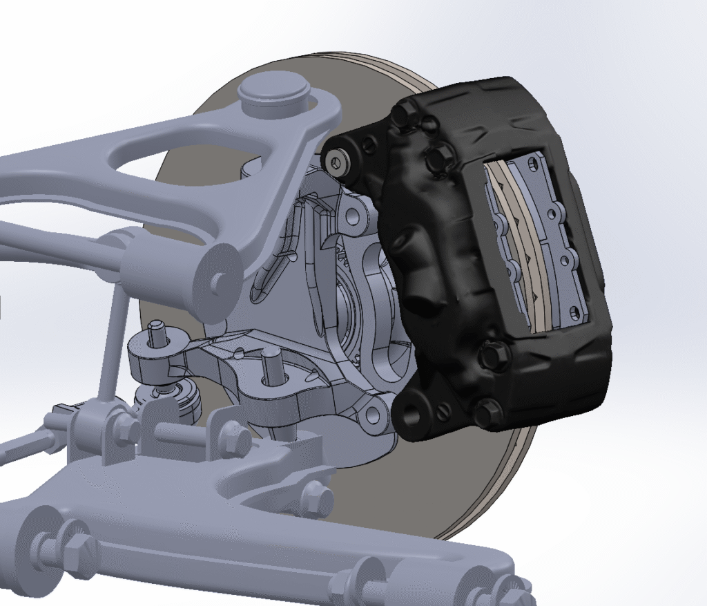
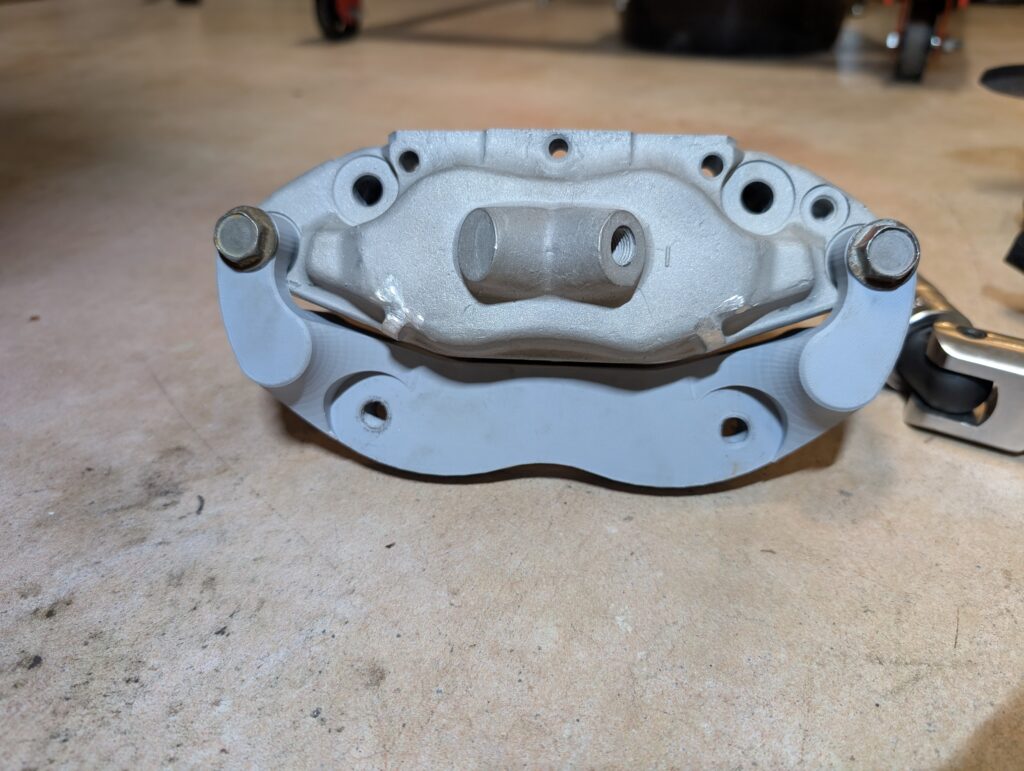
Solution 3 – Heavily Modified Calliper (My Approach)
Eventually, I explored cutting the calliper lugs off entirely. At first I wasn’t keen — it felt too extreme — but after seeing the compromises required to make other solutions work I decided to proceed.
The result was promising:
- I could now fit the factory 270mm rotor.
- 15” rims were possible (depending on offset).
- The bracket could mount via the calliper bolts.
The catch? Normally, this requires separating the calliper halves every time you change a rotor. That’s unsafe, since callipers aren’t designed to be disassembled repeatedly, and aluminium threads don’t last long under repeated torquing.
My workaround was to design the bracket so it bolts into the calliper once, effectively becoming part of the calliper. From then on, you remove it from the hub like a stock calliper.
It required a larger, more complex bracket, but it solved the major usability problem.
Engineering Considerations
Here’s where the story gets technical — and why this swap can go so wrong. The problem isn’t strength; it’s fatigue. Specifically, the endurance limit (see: Wikipedia)
- Steel has an endurance limit — below a certain stress, it can cycle indefinitely without failing.
- Aluminium does not. Every aluminium part will eventually fail, and threads are especially vulnerable.
This is why:
- Aluminium engines use studs instead of bolts.
- High-cycle parts in cars are reinforced or steel-lined.
- Aftermarket aluminium dog bones often strip threads after only a few removals.
Manufacturers usually blame “over-tightening,” but the real culprit is material fatigue. Being aware of this, I can’t in good conscience sell parts I’m aware will eventually fail when there is no user error. In defence of (some) retailers, most wouldn’t be aware of this material property and would simply pick materials based on ‘well it worked before for the other guy’ and think nothing of it, but the consequences are real regardless.
In practice, it can take as little as 3 torque cycles in aluminium before threads start to strip. There are ways to mitigate it, large diameter fasteners with coarse threads, steel inserts, or using through-hole fasteners but they all add complexity.
You can see an example of this happening with Beavis Motorsport.
https://www.youtube.com/watch?v=HDXEM1h5HeM
https://www.youtube.com/watch?v=P8kEatUWFtU
https://www.youtube.com/watch?v=vmg_P22cdS4
Since I’m aware of these issues, this dictated my material choice to be steel. Specifically I proceeded with 4340QT (which is definitely overkill) since I wouldn’t need to be concerned about pulling out threads.
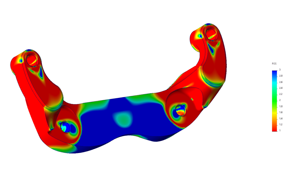
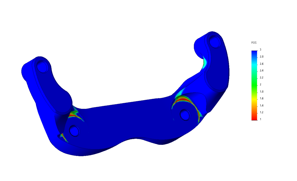
Calculating the Loads
Even though the material choice was made, I wanted to run the numbers. Calculating braking loads can be quite complex, but if we follow a very conservative and very simplified calculation:
- MX-5 mass: ~1100 kg.
- Hard braking: ~2g (19.62 m/s²).
- Front axle load share: ~70%.
- Per front wheel: ~385 kg → 7.6 kN force where the rubber meets the road.
- Wheel torque: 7.6 kN × 0.3 m ≈ 2.28 kNm.
- Rotor radius: 0.135 m → requires ~16.9 kN of force at the calliper.
In other words, each bracket must safely handle loads equivalent to 1.7 tonnes during a hard stop.
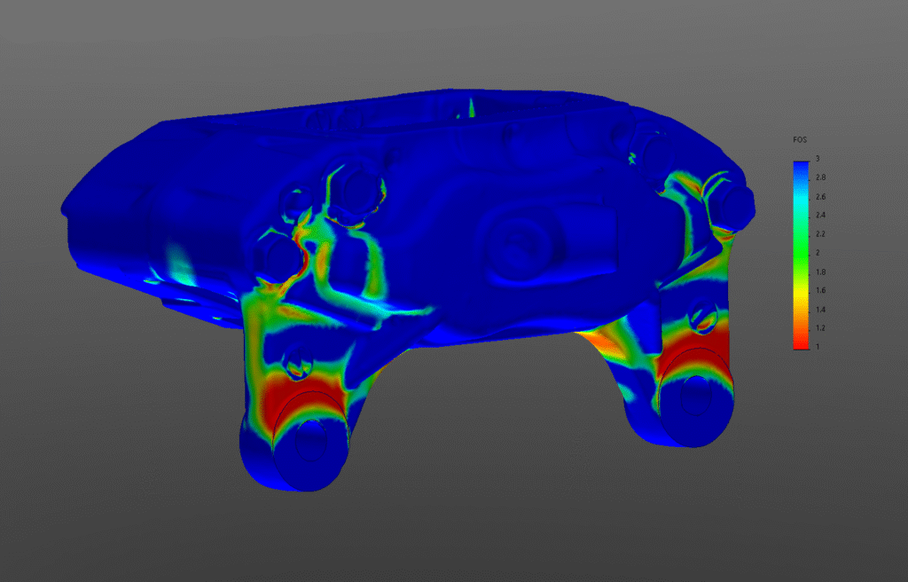
Finite Element Analysis (FEA) confirmed that aluminium (6061-T6) would be (barely) strong enough in raw numbers, but fatigue and threading issues made it unsuitable. Steel provided both strength and longevity and I wouldn’t need to complete fatigue analysis.
Piston Sizing
From a purely hydraulic and torque perspective, the gains are often overstated. When you run the numbers properly, the performance difference is minimal — and in many cases, it is fundamentally a cosmetic and aesthetic upgrade rather than a braking force upgrade.
The critical point most people miss is how a sliding (floating) caliper works. A single 54 mm piston does not simply clamp on one side of the disc; the body slides, applying equal force to the outer pad. In hydraulic terms, the clamp force is effectively equivalent to two pistons of the same area. The piston area of a 54 mm bore is approximately 2290 mm². Because the sliding mechanism doubles the clamping action, the effective area is about 4580 mm². By comparison, a four-piston caliper with 36 mm pistons has a total area of roughly 4074 mm². That’s only about an 11% reduction — far smaller than most assume when they see “four pistons” versus “one.”
What does that mean on the road? Pedal feel and hydraulic response are governed primarily by total piston area relative to the master cylinder. Because the total fluid displacement requirement is very similar, pedal travel remains essentially unchanged. Likewise, clamping force at a given line pressure is within ~10% of the factory setup, which is small enough that it often falls within the range of pad compound differences. In practical terms, the brake torque you generate is determined more by rotor diameter and pad friction coefficient than by piston count in this case.
The most common calculation error when comparing these setups is forgetting to double the effective area of the sliding caliper – a mistake I initially made. If you compare only the raw 54 mm piston area to the four individual 36 mm pistons without accounting for the floating action, you will dramatically overestimate the four-pot. This mistake leads many to assume they are gaining braking power when, hydraulically speaking, they are largely maintaining parity. The real advantages of the RX-7 caliper are typically cosmetic appeal, pad shape options, and sometimes improved heat distribution — not a transformative increase in stopping force.
It might seem surprising, but the reality of this project is that performance wise, the OEM NB 54mm front calipers are just as capable as the RX-7 calipers.
Conclusion
When I first shared this project, people asked if I’d make brackets for them. Most lost interest once they saw the cost. And that’s fair — steel, complex machining, and small production runs add up.
But that’s exactly the point. What looks like “just a simple bracket” actually requires careful design, testing, and engineering. Cutting corners with material choice might save money, but it compromises safety in ways that aren’t obvious until it’s too late.
So, instead of selling parts, I’ve decided to release the CAD models and drawings for free (non-commercial use). Any competent machinist can manufacture them. This way, you can choose materials appropriate for your budget, and I don’t have to compromise on safety. In the downloads you’ll be able to find a drawings covering critical dimensions and a .stp file. To mount this bracket to your caliper you will need two JIS Hex Flange M10-1.25 x 100 10.9 Zinc bolts.
If you can’t organise machining yourself, you’re welcome to contact me, and I can help arrange custom manufacturing.
Key Takeaways for DIYers
- Don’t just “make” parts — engineer them.
- Aluminium dog bones with threads are a ticking time bomb.
- Always check for interference in CAD or with test fits.
- Braking loads are bigger than most people think.
- Sometimes “overkill” (like using steel) is the right call when safety is on the line.